Service procedure for converting a Wills Wing T2C hang glider to T3 specification. Includes parts list, tools required, sail removal, sprog modification, bearing receptacle installation, batten length comparison tables, reassembly, and flight test guidance. Document revision r1.06 (May 2021).
Inspect all tubes carefully for damage. Report condition on traveler checklist
Service and replace tip receptacle with bearing type. Include new bolt and binding nut unless existing components are as-new
Inspect RLE sprog brackets for damage and replace if necessary
Inspect crossbar junction U and CC brackets, and bolt
Remove clean, lube and replace crossbar hinge pins
Check condition of protection/wear strips on top of crossbar and replace if necessary
Remove rear leading edges to inspect crescents. Replace with aluminum style if carbon RLE is ground to correct size.
Replace pulleys at rear of crossbar wedge unless the airframe is late-model without much use
Clean and lube keel. Report to Mike/Steve if there is significant scratching or wear to anodizing
Clean and lube rear wedge saddle
Remove UHMW concentric ring from crossbar hold-down
Replace sidewires. Check condition of all other cable assemblies and replace as necessary
If 154, check to see if the downtubes remain 68 or are reconfigured to 65
Itemize all parts replaced below
T3 154 control bar configuration option
The T3 154 is configured with the same length downtubes as the 144 which are 3 inches shorter than a T2C 154. You may choose to retain the T2C 154 68-inch length, shorten the downtubes by 3 inches or replace them. Shortening the downtubes requires trimming 3 inches in length from the top, re-machining the internal web to provide clearance for the top downtube fitting and drilling a new hole to secure the fitting with the clevis pin and safety.
The glider order must specify the configuration that you intend to adopt. The replacement sidewires for 68-inch downtubes are the same length as T2C-154s. We will provide T3 154 sidewires for 65 inch downtubes and replacement bottom front and bottom rear wires as well. The front and rear wires are optional and invoiced at standard dealer price.
General procedures
Please refer to the glider owner’s manual, make notes and take photos to be familiar and document the configuration of fasteners and assemblies as you remove them. We recommend that you replace the fastener assemblies in their original location immediately after removal or otherwise label so they are easy to identify.
Use suitable gloves and eye protection.
You will need an unobstructed area six feet by thirty feet. Make sure the surface is clean. If it is abrasive, like rough concrete, put down a protective tarp and be extremely careful not to scrape your sail or airframe.
Sail removal
Time required: 1 hour
Lay the glider on its back, unzip and remove the glider bags and put the battens and basetube aside.
Remove the screws that secure the sail at the front of the leading edges. Remove the zip-tie at the bottom nose area. Completely unzip and separate the bottom surface zipper.
Spread the wings slightly. On one side, remove the zip-tie that secures the hang loop. Open and release the quick link from the backup loop. Pull the dangling hang loop through both slots in the sail.
Dismount the sail from the rear leading edges by removing the 3/16 nut that secures the sail-mount eyebolt to the wand receptable endcap at the end of the leading edge. There will be a new 3/16 low-profile locknut with your new sail but keep these as spares.
Remove the bolt assembly that secures the inboard sprog cable and sidewire to the crossbar. There is no need to remove the rear leading edges or sprogs. Secure the sprog cable open thimble with a piece of string through the sprog fork to prevent it from turning and maintain the adjustment. Reassemble the bolt, spacer and locknut and set them aside—you’ll reinstall them when replacing the sail. Fold both sprogs backwards and in line with the sail so they won’t interfere with removing the airframe.
The control bar legs and upper VG rope need to be detached from the keel bracket to remove the sail. Untie the knot that secures the VG rope to the front noseplate. Take a photo as reference for how it is tied. Remove the clevis pin that secures the left (non-VG) leg to the top downtube fitting. Turn the top-fitting and elbow assembly to loosen the embedded locknut in the elbow fitting until it is free from the through-bolt. Replace the downtube fitting, clevis and safety, and thread the 5/16 bolt back into the nut for safe keeping.
Unbolt the bottom rear flying wires from the rear keel. Reassemble the hardware removed onto the bolt in the original order so that it doesn’t get lost. All disassembled assemblies on the glider must be reassembled in the proper order and orientation. Use the exploded parts diagrams in this manual to help you.
Slide the frame forward and out through the open center zipper. If you encounter resistance, stop and find out what is hanging up.
Remove the carbon transverse battens from the T2C sail.
Remove the nose batten from the sail
The mylar inserts cannot be exchanged between sails even of the same model. Your T3 replacement sail includes new mylar inserts and nosecone.
Remove the wand lever and cup assembly from the sail. The T3 sail includes replacement grommet inserts. The parts kit includes the associated screw (NASXXXX) and washers.
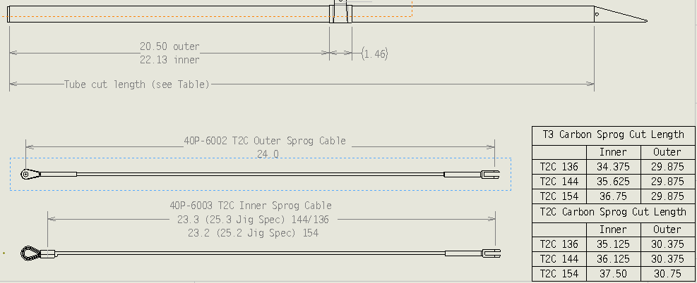
Trim sprogs to T3 length
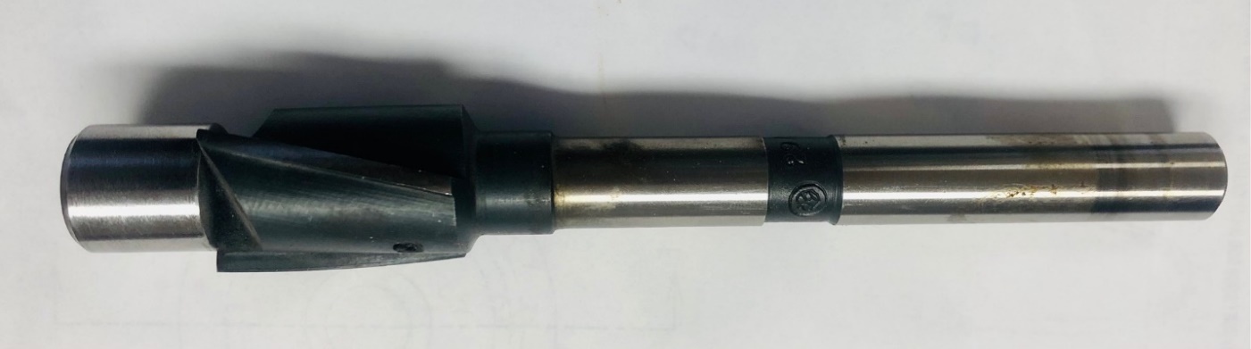
T3 sprogs are slightly shorter than T2Cs and reconfiguring them to T3 length requires replacing the rear paddles which are securely bonded in place. Cut the sprog to the new length and drill out the paddle with a piloted 17/23mm counterbore which leaves a thin residue to sand out by hand. The ID of the sprog is .919 inches, and the sprog paddle hole is 0.7 inches. Install the replacement paddles with 5 min epoxy formulated for acetal and composites.
Do not shorten that sprogs until you verify the length in the sail. The sprogs should extend past the transverse batten by at least 1/2-inch at VG tight and more at VG loose.
If you don’t have a tool like this available, then you can return the sprogs to WW for modification.
Custom drill jig used to shorten T2C sprog tubes to T3 length
Size
Inner sprog (inches)
Outer sprog (inches)
T3 136
34.375
29.875
T3 144
35.625
29.875
T3 154
36.75
29.875
T2C 136
35.125
30.375
T2C 144
36.125
30.375
T2C 154
37.5
30.75
Sprog length verification: sprog should extend past the transverse batten by approximately the diameter of the lever tip
Replace sidewires, service VG and modify transverse battens
Time required: 1 hour
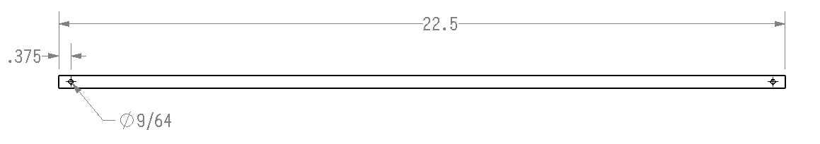
T3 transverse batten dimensions — 22.5 inches long with 9/64-inch holes 3/8 inch from each endT3 transverse battens are 0.5 inches shorter at 22.5 inches [5715mm] long with 9/64 [3.5mm] diameter holes located 3/8 inch [9.5 mm] from each end. Trim the T2C battens to T3 length with a hacksaw after wrapping the cut location with tape to minimize splintering.
The carbon tubes are weak in compression so do not overtighten if you use a vice to secure it when cutting. Use a (new) sharp drill bit and a drill guide and be aware that carbon will quickly dull most cutting tools.
Deburr the cut edges with sandpaper and install heatshrink to protect the sail.
Service the lower VG system, replacing the lower rope and downtube bracket corner bearing. References:
Closely inspect all spars and hardware for damage.
Remove rear leading edges and check condition of crescent reducers between 60mm front leading edge and carbon rear leading edge. These reducers are plastic on early T2Cs and aluminum on late model T2Cs and T3s. The option to update the crescents from plastic to aluminum depends on the configuration of the rear leading edge. The rear leading edge must have been ground to a 52 +/- 0.05 mm diameter as it was on late-model T2Cs use the aluminum crescents.
Bearing receptacle installation procedure
Time required: 1 hour
The bearing kit includes replacement wand receptacles, sail-mount endcaps, bearings and a replacement bolt and binding nut (at the bottom of the leading edge that secures the turn adjustment bolt).
We recommend that you record the wand adjustment and orientation before disassembly for reference. Our procedure is to position the closed airframe on wood blocks on a level floor, and measure from the floor to the bottom of each leading edge at the end cap, and to the bottom of the end of the wand. Alternately, if you do not have a surface that is flat and uniform enough to use as a reference then use a straight edge to the top of the rear leading edge (parallel with the tube axis) and measure the wand tip height from this reference.
The old assembly needs to be completely removed and reassembled with the replacement components. We recommend that you service each side independently.
Remove the philips-head screw that secures the orientation of the sail-mount endcap to the leading edge.
The hex head of binding nut is very shallow and requires extra care to prevent the wrench from slipping and damaging the head of the nut. Use extra care—the rear leading edge might have to be completely replaced if you strip the head on the binding nut. The procedure we use is to clamp a 7/16 socket in a vice, position the leading edge upside-down with the bolt head in the socket and use another socket to unscrew the 1/2-inch aluminum binding nut on the bottom. Be careful and use good quality tools that securely grip the fasteners.
You will re-use the top sleeve-bushing, the traveling block, the 1/4-inch bolt, and the 3/16 screw, nut and washers that secure the receptacle to the traveling block. You will discard the old lower binding nut, the wand receptacle, and wand endcap.
Inspect the turn adjustment bolt and confirm that it is straight and undamaged. The parts kit includes a replacement bolt so you only need to save the old one for parts replacement.
Dragging a leading edge on landing can break the rear leading edge in the vicinity of the turn adjustment hole. Inspect the carbon rear leading edge carefully around the hole for cracks or other damage.
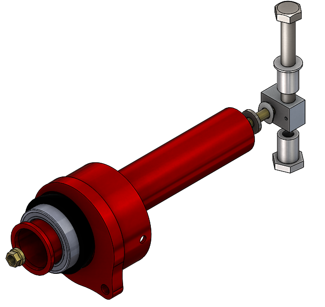
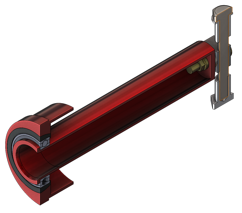
Assemble the endcap, bearing and endcap components.
Attach the receptacle to the traveling block with the NAS603-16P screw and clinch nut as shown. There are 2 washers (10U-8010 wave and 10U-1130 AN960) between the back of the receptacle and the traveling block which are not shown in the image below. Do not overtighten this assembly—it must be loose enough to allow the allow the block to move up and down on the bolt.
Set the orientation of the receptacle and block (as shown below) and slide the assembly into the rear leading edge. Align the threaded hole in the block with the hole in the tube, install the aluminum bushing into the rear leading-edge hole, then thread the bolt through the bushing and into the block. Put a few drops of oil on the threads of the new binding nut and thread it onto the bolt. Use the same procedure to tighten it as you did to remove it, with a 7/16-inch socket secured in a vice on the bottom and a 7/16 box-end wrench on top. The threads in the binding nut do not extend to the bottom of the hole so it takes a lot of force to tighten it. Verify that it is not too tight and ovalized by comparing the tube diameter in the vertical and horizontal planes.
Install the screw that secures the orientation of the endcap to the tube.
Wand bearing receptacle assembly with traveling block and binding nutWand bearing receptacle installed in the rear leading edge
Batten modifications
Time required: 2 hours
The batten modifications are the most time consuming and technically demanding service item in the upgrade process. Late model T2C-144s require very few changes in length or shape. Other configurations may require shortening many battens and reshaping others. Removing camber or reflex from a 12mm batten is possible with care and experience. Adding camber or reflex is much more difficult and most likely to break the batten so we recommend that you never try to add camber or shape to a batten. In the tables below, it may be necessary to reshape battens to the next outboard position. You can do this by holding the straight section of the batten on a flat table and gently flattening the camber working forward from the rear with your open palm. Work incrementally and check against the pattern frequently because you won’t be able to retore camber if you go too far.
Small variations in camber height within 2 batten diameters of the pattern typically have little or no effect on the flight qualities or performance so we recommend that you not attempt to reshape 12mm battens. The main concern is that corresponding battens are L/R symmetrical.
Late model T2Cs have a 13mm 7075 nose batten that is very resistant to changing shape. Earlier T2Cs have a ½-inch 6061 nose batten that typically flatten and needs to be restored to the pattern shape periodically. It is your choice to either restore the 6061 batten to the pattern shape or purchase a new 7075 batten. 6061 battens are easily identified by a bright anodizing compared to the dull anodizing on all 7075 battens.
The tables below indicate the relative lengths of late-model T2Cs relative to T3s. Earlier T2Cs, especially 144s can have different configurations include fewer battens on the top surface and different bottom surface batten configurations. We may be able to provide more information with the glider number of the original sail. In any case, always verify the batten length changes in the new T3 sail before making any modifications.
The best way to remove the threaded inserts from the rear batten is to insert a 7 x 1mm bolt and tap it out or clamp that portion in a vice as you pull on the batten. You can use also use the threaded portion of a batten tip if you don’t have a bolt. Stubborn and corroded inserts can sometime be loosened by soaking in WD40 or similar penetrating oil for a day or two.
Replace any plastic levers that are worn and fail to securely engage or lock.
Check the batten shape against the pattern.
Battens — T3 136
ID
T3 136 length (in)
T2C 136 length (in)
Difference
Correction
2
36
35.13
-0.87
Possibly ok, or reshape #3 to #2 and replace #3
3
41.06
40.81
-0.25
As above
4
46.38
46.19
-0.19
Possibly ok
5
49.25
49.56
0.31
Trim
6
52.63
52.94
0.31
Trim
7
55.88
56.19
0.31
Trim
8
58.88
59.19
0.31
Trim
9
61.5
61.94
0.44
Trim
10
64.25
64.63
0.38
Trim
11
67.06
67.25
0.19
Trim
BS1
56.88
58.5
1.62
Trim
BS2
52
52.63
0.63
Trim
Battens — T3 144
ID
T3 144 length (in)
T2C 144 length (in)
Difference
Correction
2
35.31
35.31
0
ok
3
41
41.81
0.81
ok
4
47.19
47.19
0
ok
5
50.5
50.5
0
ok
6
54.25
54.25
0
ok
7
57.56
57.56
0
ok
8
60.94
60.94
0
ok
9
63.38
63.38
0
ok
10
65.81
65.81
0
ok
11
68.63
68.63
0
ok
12
72
72
0
ok
BS3
60.63
60.63
0
ok
BS2
55.13
53.56
-1.57
New BS2
BS1
50.13
44.31
-5.82
Trim T2C BS2 to BS1
Battens — T3 154
ID
T3 154 length (in)
T2C 154 length (in)
Difference
Correction
L/R replacements with stock T2C
2
35.31
35.31
0
ok
ok
3
41
41.31
0.31
trim
5/6 ok
4
47.19
46.75
-0.44
New #4
15/16 replace
5
50.5
50.31
-0.19
Possibly ok, or reshape #5 to #4 and replace #5
7/10 ok
6
54.25
54.19
-0.06
ok
3/2 ok
7
57.56
57.69
0.13
trim
3/2 ok
8
60.94
60.94
0
ok
4/2 ok
9
63.38
63.69
0.31
trim
6/7 ok
10
65.81
66.25
0.44
trim
13/8 ok
11
68.63
68.94
0.31
trim
10/11 ok
12
72
73.13
1.13
trim
9/10 ok
BS3
60.63
61.44
0.81
trim
Too short by ~ .75in
BS2
55.13
56.31
1.18
trim
ok
BS1
50.13
51
0.87
trim
Trim 0.5
NA
0
44.25
ACLER installation
Time required: 30 minutes
The optional ACLER carbon-Kevlar leading edge supports need to be attached to the mylar with double sided tape. See the ACLER installation instructions (PDF).
Airframe prep and reassembly. Sprog, wand settings and other tuning
Time required 3 hours
Inspect the airframe thoroughly including removing any fasteners and other hardware to verify that they are undamaged and installed properly.
Check that that the sprog and crossbar brackets are undamaged and that the rivets are secure.
Check the condition of the haul-back cable. Replace if there are kinks, bends or other damage.
Check the condition of all pulleys especially the 2 installed in the rear of the keel beam. The service life of these pulleys is commonly between 300 and 600 hours of airtime. The other pulleys typically have a longer life expectancy.
Remove, clean, and grease the crossbar hinge pins, and replace.
Clean and lubricate the keel with SailKote.
Set the orientation of the wands by adjusting the turn adjustment screw so that the wands are parallel with the axis of the rear leading edge. With the airframe closed and resting right-side-up on blocks on a level surface, verify that both wands are parallel and the same height.
The airframe will be inserted into the sail upside-down, with the wings slightly spread and the sprogs folded back and in-line with the leading edges. We recommend that you secure padding around the crossbar, sprog, and other hardware junctions to protect the sail as the airframe is inserted. If available, it helps to position the frame on cardboard packing tubes to allow you to move the airframe into the sail without sliding it on the ground.
If so equipped, ACLER inserts must be attached to the mylar before it is installed in the sail. Install the mylar incrementally until is past the edge of the pocket hem and reaches the tip. Check for folds and creases and verify that the mylar insert is free floating and not binding in any area.
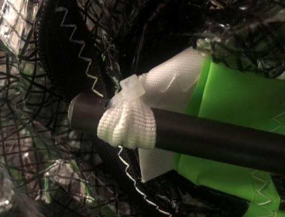
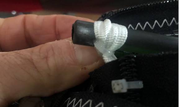
Refer to the photos below for installing and securing the transverse battens to the tabs in the sail with zip-ties.
Transverse batten secured to sail tab with zip-ties — overhead viewTransverse batten zip-tie attachment detail
Install the tip lever assemblies. Note the orientation of the fasteners and stacking order of washers which is important for the raked tips. Hold the grommet inserts to prevent spinning when tightening the screw that secures the lever. Installation is much more difficult if you cross-thread the screw or let them slip. When installed as intended, the screw is entering the pressed in clinch nut from the “wrong” side. One way to reduce the chance of cross threading is to first install the screw in the opposite direction, then remove it and install it in the intended direction. This will make it easier for the screw to “find” the correct orientation to the threads as it goes in.
Fold the sail to match the orientation of the airframe (keel pocket up) and position it immediately behind.
Slide the airframe slowly and incrementally into the sail. Stop immediately if you feel resistance. Periodically reposition and guide the leading edges past any obstructions in the bottom surface like the shear ribs. The keel must be guided into the keel pocket and the sprogs deployed out through the associated openings as the airframe is installed.
When the airframe is fully installed, secure the sail-mount eyebolt to the leading-edge endcap tab. Verify that the sail mount is not twisted around the leading edge. The factory tension is 2-3 threads past the top of the nut. At the nose, use a temporary cord to pull the sail as far forward and close to the sail mount holes as possible and tie it in position.
Install the large zip-tie at the front of the bottom surface and tighten it util the space between the hems is the same as the remainder of the zipper.
Check that the keel pocket strap is not tight during assembly or it could damage the sail. After complete assembly, it should be about 1/2-inch slack at VG loose and just snug at VG tight. Install the rear keel bolt through the bottom rear wire tang, keel pocket tang, keel and into the keel nut assembly at least a few turns (finger tight).
You should have already installed the replacement sidewires and VG rope at this time. Install the basetube onto the downtubes and flip the glider up onto the bar.
Thread the sidewires though the sail and, together with the inboard sprog cable, bolt to crossbar with the associated washer and spacer as shown in the manual. Do not overtighten this or any other assembly. The proper tension should be enough to engage the nylock and not more than 1 turn tighter than you can turn the assembly by hand.
Apply a drop of red Loctite to the rear wire junction keyhole-nut threads and tighten 1 turn past being able to turn by hand. The end of the bolt should be between even and 2 turns past the end of the nut threads. Thread the sweep wire through the keel pocket.
Re-install the hang loop on the spreader with zip-tie and secure the backup with the quicklink. Be sure to install the zip ties that retain the main hang loop. The elevated hang system should be mounted in the middle hole on the keel.
Remove the plastic spacer that serves as a VG range limiter on T2Cs.
Verify that all sprog zippers are closed, and the shear Velcros are properly mated.
Carefully tension the wing making sure that the nose area of the sail is not too tight or caught on any hardware. Install the sail mount screws at the nose. Install the nose batten while pushing down on the rear so it doesn’t stress the sail.
Release the sweep wire, install, and adjust the battens and complete the assembly of the glider.
Tie the nosecone to the loop on the sail using the line provided in a position that is secure and without gaps along the perimeter. You can find the ideal position by holding it in the palm of your hand while moving it against the sail. In the ideal position, the bottom Velcro will mate within a few mm.
Check that that the sprogs are set to 5 degrees inner and 7 degrees outer relative to the rear keel when measured at VG tight.
Assemble the tip levers with (2) 10U-5084 washers on top and (1) 10U-5103 below
Initial flight tests should only be conducted with the glider configured with factory-stock wand, sprog, batten, CG and keel pocket settings. Do not configure the glider to match expectations based on previous settings or experience.
Every flight test should begin with a thorough preflight inspection to verify proper assembly, symmetry, tuning and other potential irregularities. Follow the procedural guide in the owner’s manual.
Your test flight should include at least 15 minutes of soaring in convective lift where you can evaluate the lateral control and other qualitative characteristics of the T3. Compared to a typical T2C, the control should be relatively quick and more responsive with a noticeable ability to initiate turns with less effort and lag time, and this advantage should become more pronounced at higher VG settings.
Check for low-speed lateral trim (turns) by noting any difference in lag and effort required to initiate a turn between left and right and any difference in roll stability while in steady-state thermalling turns.
Check for high-speed lateral trim at VG tight between 40-50 mph.
If you have a laminate window bottom surface, note the sprog cable tension throughout the VG range. For pilots at the bottom end of the weight range, the cables should be slack at all VG settings progressively becoming almost tight at full VG. The cables typically become looser as twist increase from drag loads at speeds especially above 60 mph.
Note and record the following information during your flight test.
Minimum controllable and sustainable speed at VG loose, wings level, typically stall speed plus 0.5 to 1 mph. Check for stall hysteresis which is indicated by a delayed recovery at a relatively higher speed than typical.
Hands-off (or stabilized) trim speed at VGL, VGM and VGT. We typically reference lower speeds relative to stall speed. For example, for Steve at 175 lbs. hook-in, T3 144 trim at VGL is typically stall plus 2 mph, increasing progressively to stall + 3-5 mph at VGT.
Vd, top steady-state speed at VGT with pilot full-forward but not but ‘balled-up’. Also pitch bar pressure at Vd reported in lb.-per-hand. Vd typically ranges from 68 to 75 mph with 3-5 lbs. per hand return to trim pressure.
Reports from two dealers who completed the conversion
The T3 upgrade went really well. The longer T2C sprogs have a lump in the sail and could catch in the sail if battens were dimensioned so I cut them.
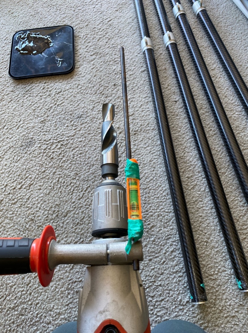
I bought a 23mm drill bit and had the first 30mm turned down by a toolmaker to 17mm for the piloting part. The toolmaker also made a cutting edge on the start of the 23mm section. It worked well. I practiced first on blocks of wood predrilled with a 17mm hole, then on some acrylic plastic that I had.
I cut the sprog paddle off at where the angle cut started to give a little more room to get the drill started accurately. The drill I used has a guide which I used to align laterally, and I fit it with a spirit level to watch the vertical angle. I ran the drill at a relatively low speed in case it lurched through the plastic and drilled in short sections to prevent heat buildup. It drilled perfectly leaving a thin sliver of plastic inside the sprogs which I was able to get a knife edge under and peel out. There was a little glue left to file out with a half round file.
This had potential for disaster but came out well so I’m now well equipped for the next.
Many of the battens had to be shortened to allow some adjustment, I’m getting good at this now. I put the batten rear end on top of the vice (plastic lever tip still inside) with the punch dent upward and I hammer the dent a bit flatter. Then I clamp the alloy threaded insert in the vice and pull the batten. If it dosn’t pull out the first time, another few taps at the same point with a hammer does the job. Then I usually cut 5mm off the batten and put the threaded insert and lever tip back in and re-punch 5mm along from the old location. I’ve found a single wrap of paper masking tape is the quickest way to stop the looseness of the thread on the lever tip insert.
The other day I test flew the T3, the wind dropped shortly after launch to about 7 knots but I was able to stay soaring while most went down. The glider seemed to trim perfectly and coordinated well in shallow turns even at higher VG settings. It was a relief to find that the wand angles I copied from the old glider setup worked. This part had me worried as I have another T2C144 here that has wands with the tips about 15mm higher than the glider I was working on. This T2C now trims very nose light with the 3mm shorter wands. I’m interested to hear what your standard position for the wands is?
I’ve been checking with a straight edge clamped on the bottom of the outer leading edge at the adjustment bolt while upside down and with the T2C to T3 update it was 18mm from the straight edge to the middle of the wand tip. The T2C measured 40mm so its wands are about 20mm higher. This T2C seemed to handle better with the 3mm shorter wands but I don’t think I should give it to the new owner with the bar trim position so far out. I’ll get one more chance to adjust and test fly it before he comes to town to pick up so I’m wondering whether the best option is to put the standard length wands back in or to lower the tip wands to the same position as the other gliders? I suspect the shorter wands are having the most effect by allowing more washout and that lowering the wands may not make enough difference. The outer battens are noticeably looser with the 3mm shorter wands so perhaps tightening battens as well as lowering the wands a little? I’ve tightened the leading edge attachment from 1mm to 2.5mm also which may also contribute to the nose lightness.
Handling of the new T3 was absolutely superb. I think the owner will be as thrilled as i am with the way it flies. He’s a well-respected comp pilot and instructor so I’m sure this will lead to more sales.
Thanks so much for designing such a great glider.
Cheers,
Bill
Bill Degen with the completed T3 conversion in New Zealand
Daniel Vélez Bravo with the completed T3 conversion in Colombia
We finished the T3 conversion without any issues. The Sprogs cutting and bonding was the slowest part of the process as we needed a good industrial workshop that could remove the internal residue of the old tip before inserting the new one.
The only worry was that the sprog measuring that is on the manual seems a little on the "short" side. So even when configuring the sprogs to 7° and 5°, the carbon rod and the webbing that supports the sprog into position were resting on the plastic tip, just 2 cm from the tip. It looks nicer as it´s somehow flatter on the sail, but maybe too short?
Anyway, it felt strong and confident enough. I couldn´t force the carbon rod to "jump off" the sprog.
One suggestion... The sprog tips are too sharp on the edges. I got a cut on a finger moving it, and the customer got a small crease on the under sail moving the sprog into position while producing friction to the sail with the carbon rod and the sprog tip. Maybe you could "round up" a little the edges of the plastic ending so it wont be so "sharp". We are going to do that eventually on this glider (sandpaper or something similar to the edges).
Why 3 lower battens? My T3 has only 2. Are we back at 3 battens for any special reason?
Today I did the test flight of the newly born T3.
I prefer hanging on the back but i flew it on the middle as the customer likes it that way.
The glider behaves perfect. VG really smooth (like brand new glider). The trim was a little higher than my current T3, probably because hanging on the middle, and even when the sprogs where conservatively 7° and 5°, the trim from no VG to Full VG changed from 47-48kph to 65-67 kph (airspeed).
I could slow down easily to almost 38kph and had some lateral control, before starting to stall.
So all in all, a really good glider and an incredible straight forward conversion process.
It felt solid, straight, no turning whatsoever, visibly balanced, pure racing machine.
I've just set the wands on a T3 154 using the factory method - bare frame on blocks, measuring from the floor to the bottom of the wands. Same method and spec for all T3's.
With a straightedge held against the last 3.5" of the RLE the bottom of the wand tip just touches the straightedge (see image below)
This should get one "in the ballpark" if trying to reset the wands without pulling the frame. The bumps on the RLE farther in would make placing the straightedge farther in (more) unreliable. One could do this with the glider intact, just dismount the tips.
I generally see 8mm of tip-height change per full turn of the adjustment bolt. There is a little play in the linkage, so I get the tips below the spec and then raise them. The first 1/4 turn when reversing bolt-turning direction usually doesn't change the tip height, but it varies.
As far as that T2 you mention with the wands being much higher, that makes some sense because the T3 spec is 16mm ("two turns") down from what the T3 (originally) was.
Wand height set with a straightedge against the last 3.5 inches of the rear leading edge
This document was authored by Wills Wing engineering. For questions about T2C-to-T3 upgrades, contact Wills Wing or your authorized dealer. The PDF above is the canonical reference; this web page reproduces its content for online reading.